[:de]Glattrohr oder genuteter Extruder Zylinder – Wann, welcher und warum?[:en]Smooth barrel extruder or grooved barrel extruder – when, which one, and why?[:]
[:de]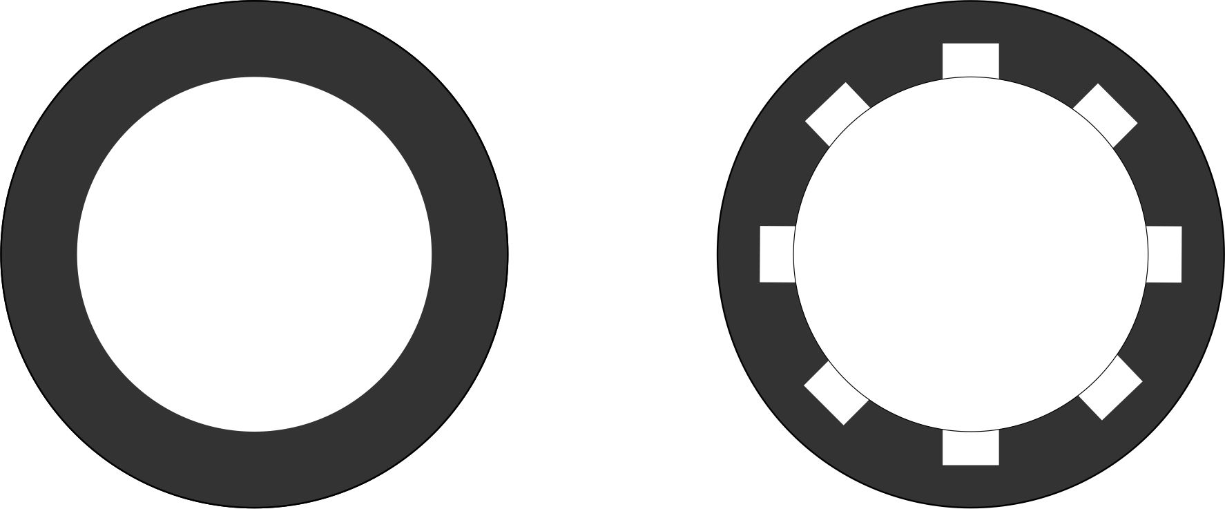
Bei Extrusionszylindern wird generell unterschieden in Glattrohrextruder (konventioneller Extruder) und in genutete Extrusionszylinder (Nutbuchsenextruder, Helibar, etc.). Die Unterschiede der verschiedenen Systeme liegen, wie der Name schon nahelegt, in der Gestaltung des Extruderzylinders. Während der konventionelle Extruder einen vollständig glatten Zylinder besitzt, sind bei einem genuteten System auf der Innenseite des Zylinders Nuten eingebracht. Welche Vorteile die verschiedenen Systeme besitzen und wann diese eingesetzt werden, ist Inhalt dieses Artikels.
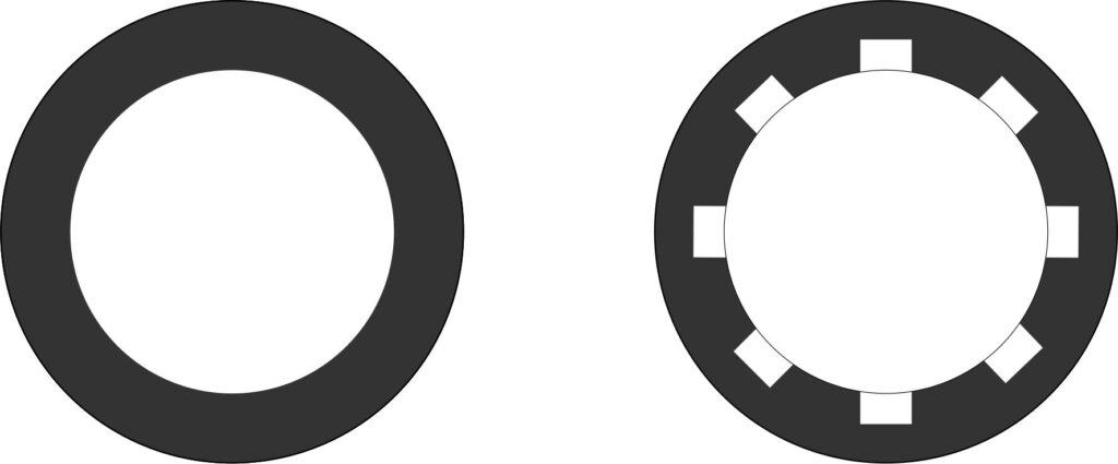
(Obere Abbildung: Schnitt durch Extrusionszylinder (schematisch), links: Glattrohr ohne Nuten; rechts: Zylinder mit axialen Nuten)
Aus geometrischer und fertigungstechnischer Sicht können Extrusionszylinder in die beiden Gruppen:
- glatte Zylinder ohne Nuten
- genutete Zylinder (mit unterschiedlichsten Nutengeometrien)
unterteilt werden.
Geometrie, Anzahl, Verlauf und Form der Nuten
Die Form, die Anzahl, der Verlauf und die Länge der Nuten können dabei sehr unterschiedlich sein.
Als mögliche Nutenformen kommen rechteckige-scharfkantige, rechteckige-abgerundete, halbkreisförmige, trapezförmige und weitere Sonderformen zum Einsatz, die sich zudem in der Breite, Tiefe und der Anzahl über dem Innenumfang unterscheiden können.
Hinsichtlich des Verlaufes sind rein axiale Nuten aber auch wendelförmig über den Innenumfang verlaufende Systeme (Helix) etabliert.
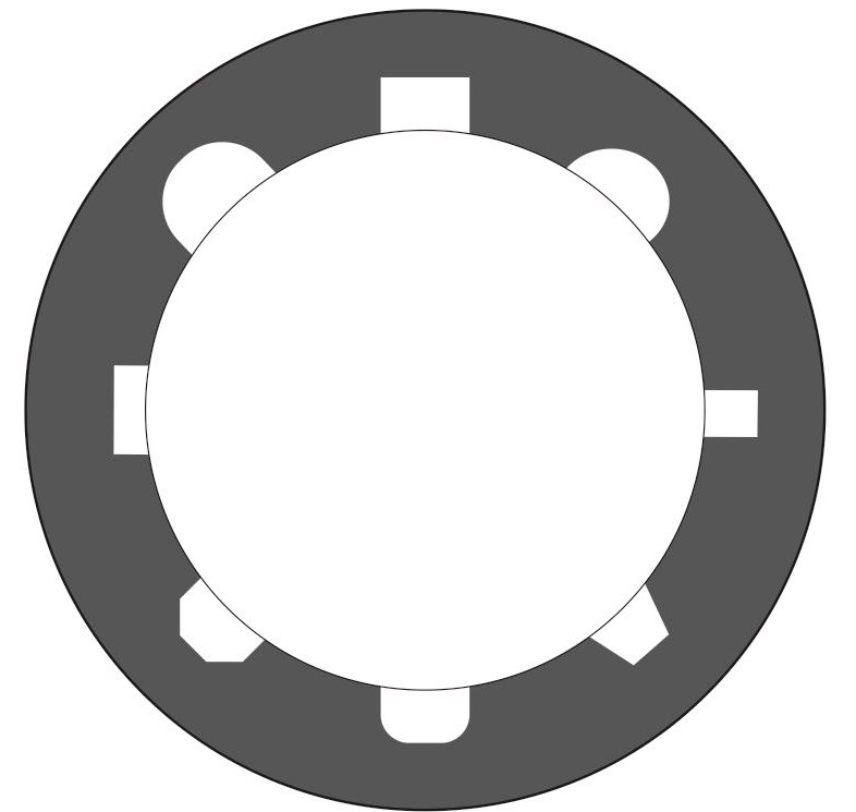
Abbildung zeigt verschiedene Geometrieformen die für Nuten eingesetzt werden
Die Länge der Nuten kann dabei ebenfalls sehr unterschiedlich sein. Oft endet der genutete Bereich am Ende der Einzugszone wobei die Nuttiefe dann ausgehend von einer Anfangstiefe kontinuierlich bis auf den Innendurchmesser des Zylinders abnimmt. Aber nicht immer verringert sich die Tiefe der Nut kontinuierlich und läuft auf den eigentlichen Kerndurchmessers des Zylinders aus. In einigen Fällen werden die Nuten auch bis zum Ende des Extruders durchgezogen.
Was passiert im Extruder mit dem Granulat, wenn der Zylinder glatt oder genutet ist?
Eine der wichtigsten Aufgaben eines Extruders ist es, den Kunststoff von der Einfüllöffnung zur Düse zu fördern. Damit ein schneckenbasiertes System in der Lage ist, eine axiale Förderung zu realisieren, ist es erforderlich die in den Schneckengängen befindliche Kunststoffmasse daran zu hindern, dass diese sich “mitdreht” und somit auf einer Kreisbahn rotiert, anstatt axial gefördert zu werden.
Als anschauliches Beispiel kann dabei das Schraube-Mutter Modell verwendet werden. Befindet sich eine Mutter auf einer Schraube und die Schraube wird gedreht, dreht sich die Mutter mit der gleichen Geschwindigkeit, ohne dass diese axial auf der Schraube bewegt wird. Wirkt jedoch eine Widerstandskraft (Reibung) auf die Mutter, so tritt die Situation ein, dass die Schraube langsamer rotiert und gleichzeitig in axialer Richtung verschoben wird. Sofern ein Formschluss eine Rotation der Schraube vollständig verhindert, tritt eine reine axiale Bewegung der Mutter ein.
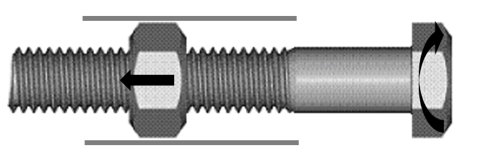
Abbildung: Schraube-Mutter Modell, als anschauliches Beispiel für die Förderung von Granulat in einem Extruder (nach: Chris Rauwendaal)
Übertragen existieren also drei mögliche Situationen der Granulatbewegung innerhalb eines Extruders:
- Das Granulat wird nicht axial gefördert, sondern folgt einer Rotationsbahn um die Schnecke herum. Dieser Extrem-Zustand würde erfordern, dass die Reibkräfte zwischen Granulat und Schnecke sehr viel größer sind als die Reibkräfte zwischen Granulat und Zylinder.
- Das Granulat wird rein axial gefördert und das Granulat bewegt sich nicht auf einer Kreisbahn wie die Schnecke. Dieser Extremzustand würde erfordern, dass die Reibkräfte zwischen Zylinder und Granulat sehr viel größer sind als die Reibkräfte zwischen Granulat und Schnecke.
- Das Granulat wird sowohl axial gefördert, es findet aber auch eine rotierende Bewegung statt.
Die dritte genannte Option tritt üblicherweise in der Praxis in einem Extruder auf. Das Granulat wird axial gefördert, bewegt sich aber dennoch auch auf einer Kreisbahn. Die Granulaförderung findet somit auf einer Spiralbahn vom Extrudereintritt zur Düse statt. Die zweite Option kann ausschließlich bei Nutbuchsenextrudern auftreten und auch nur, wenn durch die Geometrie der Nuten die kreisförmige Bewegung vollständig unterbunden werden kann.
Mit den oben aufgeführten Erläuterungen ist nun verständlich, welche Wirkung eine genutete Einzugszone haben kann. Durch die genutete Gestaltung der Zylinder-Innenoberfläche gelangen Granulatkörner in die Nuten, wobei die (axialen) Nuten verhindern, dass das Granulat sich in Umfangsrichtung bewegen kann. Eine Rotationsbewegung des Granulates wird somit erschwert und eine axiale Bewegung des Granulates erzwungen.Zudem entsteht im eigentlichen Schneckengang eine “Verkeilung” die ebenfalls eine axiale Förderung begünstigt.
Die genauen Abläufe innerhalb der Nuten lassen sich dabei je nach Tiefe der Nuten im Verhältnis zur Größe des Granulates unterscheiden. Wie genau die Ausführung der Nuten einen Einfluss auf die Förderung haben kann, folgt in einem weiteren Beitrag.
Vereinfachend kann festgehalten werden, dass ein Nutbuchsenextruder aufgrund der Gestaltung der Zylinder-Innenoberfläche eine Vergrößerung der Reibung (bzw. sogar eine Art Formschluss) realisieren kann, wodurch die axiale Förderwirkung erhöht und die umfangsgerichtete Bewegung des Granulates verringert wird. Der Nutbuchsenextruder wird folglich auch als “fördersteifer Extruder” bezeichnet und es wird von einer “Zwangsförderung” gesprochen.
Druckaufbau im Glattrohrextruder und Nutbuchsenextruder
Aufgrund der oben genannten Situation, existiert in Glattrohrextrudern und Nutbuchsenextrudern ein sehr unterschiedliches Druckaufbauverhalten. Im Glattrohrextruder wird der Druck kontinuierlich über die Länge der Schnecke aufgebaut und erreicht im letzten Bereich des Extruders den maximalen Schmelzedruck. Im Nutbuchsenextruder hingegen wird der maximale Druck bereits früh erreicht und baut sich dann im weiteren Verlauf des Extruders bzw. des Extrusionswerkzeuges wieder ab.
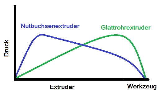
Abbildung: Druckaufbau im Glattrohrextruder und Nutbuchsenextruder (schematisch)
Ein besonderer Vorteil, den der Nutbuchsenextruder besitzt ist, dass im Nutbuchsenextruder der Druckaufbau und damit auch der Massenstrom unabhängig vom Gegendruck des Werkzeuges konstant ist. Dieser besondere Vorteil macht den Nutbuchsenextruder für gewisse Anwendungen, in denen der Gegendruck variiert (z.B. bei verstellbaren Düsen zur Wanddickensteuerung beim Blasformen) sehr gut einsetzbar.
Aufgrund des Druckaufbauverhaltens des Nutbuchsenextruders resultieren jedoch auch gewisse Nachteile, wie beispielsweise eine verringerte Mischleistung des Extruders. Dadurch, dass beim Glattrohrextruder am Ende des Systems der maximale Druck vorherrscht, strömt kontinuierlich ein kleiner Teil des bereits aufgeschmolzenen Materials wieder in Richtung Einzugszone (z.B. über die Leckspalte der Schnecke), so dass eine verbesserte Durchmischung erreicht werden kann. Im Nutbuchsenextruder ist die aus dem Druck resultierende Strömungskomponente mit der Förderrichtung gleich gerichtet. Somit entsteht hier keine zusätzliche Mischung, so dass oft zusätzliche Mischteile eingesetzt werden müssen.
Nutbuchsenextruder oder Glattrohrextruder
Grundsätzlich weisen beide Extruderkonzepte gewisse Vor- und Nachteile auf und besitzen einen ähnlichen, sich überschneidenden Einsatzbereich. Somit ist für viele Anwendungen nicht genau klassifizierbar, ob ein genuteter Einzugsbereich nun das Mittel der Wahl oder ein glatter Extruder die besseren Ergebnisse zeigt. In vielen Betrieben ist es in der Praxis auch üblich, dass ein und das selbe Produkt sowohl auf Glattrohrextrudern als auch auf Nutbuchsenextrudern produziert werden kann.
Nutbuchsenextruder: Vorteile, Nachteile, Einsatzbereiche und Grenzen
- Nutbuchsenextruder gilt als “Feststofffördermaschine”
- tendenziell sind höhere Massedurchsätze möglich
- gut bei Material mit geringem Reibungskoeffizienten (Material rotiert nicht mit der Schnecke, Förderwirkung bleibt hoch)
- Massedurchsatz soll möglichst unabhängig vom Gegendruck sein (z.B. bei während der Extrusion variierenden Düsenweiten, beim Einsatz von Filtern die sich zusetzen, etc.)
- hohe Förderleistungen sind möglich
- Extruder arbeitet mit hoher Konstanz, Massedurchsatz ist nur von der Drehzahl abhängig (ähnlich einer Pumpe)
- Einsatz ist meist nur bei Granulaten möglich (kein Recyclingmaterial, kein Randbeschnitt, etc), da das System sehr empfindlich auf Schüttdichteschwankungen reagiert und somit die Durchsatzkonstanz gefährdert ist
- der Einsatz von zusätzlichen Schmelzepumpen ist meist nicht notwendig
- in der Regel ist eine Kühlung der Nutbuchse (meist wassergekühlt) erforderlich, teilweise ist auch eine Temperierung mittels Temperiergeräten sinnvoll
- kleine bis mittlere Maschinengrößen verfügbar
- Nutbuchsenextruder wurden ursprünglich für die Verarbeitung von PE und PP entwickelt und werden bis heute auch schwerpunktmäßig dafür eingesetzt (aber nicht ausschließlich)
- Verarbeitung sehr harter Materialien (z.B. viele amorphe Materialien) bedingt möglich, spezielle Erfahrungen notwendig
- es können teilweise sehr hohe Drücke auftreten
- es können Drehmomentspitzen auftreten
- erhöhter Verschleiß
- gilt im Bereich der Blasfolienextrusion und beim Blasformen als Standard
Glattrohrextruder: Vorteile, Nachteile, Einsatzbereiche und Grenzen
- Glattrohrextruder gilt als “Schmlzefördermaschine”
- Mischwirkung des Extruders ist sehr gut
- Schüttdichteschwankungen sind meist unproblematisch, z.B. Verarbeitung von Recycling-Material, Randbeschnitt, Flakes, etc.
- sehr universell
- einfaches, kostengünstiges langlebiges System
- keine zusätzliche Kühlung notwendig
- kann eingesetzt werden, wenn die oben genannten spezifischen Vorteile des Nutbuchsenextruders nicht notwendig sind
- Veränderungen im Gegendruck führen zu Veränderungen im Durchsatz (z.B. bei sich zusetzenden Filtern)
Wenn Sie Interesse an weiteren Informationen und kostenlosem Downloadmaterialien haben oder automatisch beim Erscheinen neuer Beiträge informiert werden möchten, melden Sie sich hier für unseren Premiumbereich und Newsletter an.[:en]
Extrusion cylinders are generally divided into smooth barrel extruders (conventional extruders) and grooved extrusion cylinders (grooved barrel extruders, helibars, etc.). The differences between the different systems lie, as the name suggests, in the design of the extruder barrel. While the conventional extruder has a completely smooth cylinder, a grooved system has grooves on the inside of the cylinder. What advantages the different systems have and when they are used is the content of this article.
Upper illustration: Section through extrusion cylinder (schematic), left: plain tube without grooves; right: cylinder with axial grooves)
From a geometric and manufacturing point of view, extrusion cylinders can be divided into the two groups.
- smooth cylinders without grooves
- grooved cylinders (with different groove geometries)
Geometry, number, course and shape of grooves
The shape, the number, the course and the length of the grooves can be very different.
Rectangular-sharp-edged, rectangular-rounded, semi-circular, trapezoidal and other special shapes are used as possible groove shapes, which may also differ in width, depth and number over the inner circumference.
With regard to the course, purely axial grooves but also helical systems running over the inner circumference (helix) are established.
Illustration shows different geometric shapes which are used for grooves.
The length of the grooves can also vary greatly. Often the grooved area ends at the end of the feed zone and the groove depth then decreases continuously from an initial depth to the inner diameter of the cylinder. However, the depth of the groove does not always decrease continuously and runs out to the actual core diameter of the cylinder. In some cases, the grooves are also drawn through to the end of the extruder
What happens to the granules in the extruder when the cylinder is smooth or grooved?
One of the most important tasks of an extruder is to convey the plastic from the feed opening to the nozzle. In order for a screw-based system to be able to realize axial conveying, it is necessary to prevent the plastic mass in the screw flights from “rotating” and thus rotating on a circular path instead of being conveyed axially.
The screw-nut model can be used as an illustrative example. If a nut is on a screw and the screw is turned, the nut rotates at the same speed without moving it axially on the screw. However, if a resistance force (friction) acts on the nut, the situation occurs that the screw rotates more slowly and is simultaneously displaced in the axial direction. If a positive fit completely prevents rotation of the screw, pure axial movement of the nut occurs.
Illustration: Screw-nut model, as an illustrative example for conveying granulate in an extruder (according to: Chris Rauwendaal)
Three possible situations of granules movement within an extruder can therefore be transferred:
- The granulate is not conveyed axially, but follows a rotary path around the screw. This extreme condition would require that the frictional forces between granulate and screw are much greater than the frictional forces between granulate and barrel.
- The granulate is conveyed purely axially and the granulate does not move in a circular path like the screw. This extreme condition would require that the frictional forces between barrel and granulate are much greater than the frictional forces between granulate and screw.
- The granulate is conveyed axially, but there is also a rotating movement.
The third option usually occurs in practice in an extruder. The granulate is conveyed axially, but still moves on a circular path. The pellets are thus conveyed along a spiral path from the extruder inlet to the die. The second option can only occur with grooved barrel extruders and only if the circular movement can be completely prevented by the geometry of the grooves.
With the above explanations it is now understandable what effect a grooved feed zone can have. The grooved design of the inner surface of the cylinder allows granules to enter the grooves, whereby the (axial) grooves prevent the granules from moving in the circumferential direction. A rotational movement of the granulate is thus made more difficult and axial movement of the granulate is forced.
The exact processes within the grooves can be distinguished according to the depth of the grooves in relation to the size of the granulate. How exactly the design of the grooves can have an influence on the conveying follows in another article.
To simplify matters, it can be stated that a grooved-barrel extruder can increase friction (or even a kind of positive fit) due to the design of the inner cylinder surface, which increases the axial conveying effect and reduces the circumferential movement of the pellets.
Pressure build-up in smooth tube extruders and grooved sleeve extruders
Due to the above mentioned situation, there is a very different pressure build-up behaviour in smooth barrel extruders and grooved barrel extruders. In the smooth barrel extruder, the pressure is continuously built up over the length of the screw and reaches the maximum melt pressure in the last area of the extruder. In the grooved barrel extruder, on the other hand, the maximum pressure is reached early and is then reduced again in the further course of the extruder or extrusion die.
Illustration: Pressure build-up in a smooth tube extruder and grooved bush extruder (schematic)
A particular advantage of the grooved-barrel extruder is that the pressure build-up in the grooved-barrel extruder and thus also the mass flow is constant regardless of the counter-pressure of the die. This special advantage makes the grooved barrel extruder very suitable for certain applications in which the counterpressure varies (e.g. with adjustable nozzles for wall thickness control during blow molding).
However, due to the pressure build-up behaviour of the grooved barrel extruder, certain disadvantages also result, such as a reduced mixing capacity of the extruder. Because the maximum pressure prevails at the end of the system in a smooth tube extruder, a small part of the material already melted flows continuously back towards the feed zone (e.g. via the leakage gap of the screw), so that improved mixing can be achieved. In the grooved barrel extruder, the flow component resulting from the pressure is directed in the same direction as the conveying direction. This means that no additional mixing is required, so that additional mixing parts often have to be used.
Grooved barrel extruder or smooth tube extruder
Basically, both extruder concepts have certain advantages and disadvantages and have a similar, overlapping area of application. Therefore, it is not possible to classify precisely for many applications whether a grooved feed area is the medium of choice or a smooth extruder shows the better results. In many companies it is also common in practice that one and the same product can be produced on smooth barrel extruders as well as on grooved barrel extruders.
Grooved barrel extruder: advantages, disadvantages, areas of application and limits
- grooved-barrel extruder is considered a “solids conveyor”.
- higher mass throughputs tend to be possible
- good for material with low coefficient of friction (material does not rotate with the screw, conveying effect remains high)
- mass throughput should be as independent of back pressure as possible (e.g. with nozzle widths varying during extrusion, when using filters that become clogged, etc.)
- high conveying capacities are possible
- extruder operates with high consistency, mass flow rate depends only on the speed (similar to a pump)
- use is usually only possible with granulates (no recycled material, no edge trimming, etc.), since the system reacts very sensitively to fluctuations in bulk density and therefore the throughput constancy is endangered
- the use of additional melt pumps is usually not necessary
- usually cooling of the grooved bushing (usually water-cooled) is required, in some cases temperature control by means of temperature control units is also useful
- small to medium machine sizes available
- grooved barrel extruders were originally developed for the processing of PE and PP and are still mainly used for this purpose (but not exclusively)
- processing of very hard materials (e.g. many amorphous materials) conditionally possible, special experience necessary
- very high pressures can occur in some cases
- torque peaks can occur
- increased wear
- is considered as standard in the field of blown film extrusion and blow moulding
Smooth tube extruders: advantages, disadvantages, areas of application and limits
- smooth-barrelextruder is considered a “melt conveying machine”.
- mixing effect of the extruder is very good
- bulk density fluctuations are usually unproblematic, e.g. processing of recycled material, edge trimming, flakes, etc.
- very universal
- simple, cost-effective, long-lasting system
- no additional cooling necessary
- can be used if the specific advantages of the grooved bush extruder mentioned above are not necessary
- changes in back pressure lead to changes in throughput (e.g. with clogging filters)
If you are interested in further information or if you want to be kept informed about new articles, please register for our newsletter and our free download area.
[:]