[:de]Wie Sie die maximale Produktionsgeschwindigkeit eines Profils ermitteln[:en]How to calculate the maximum line speed for a new extruded profile[:]
[:de]
Bei der Extrusion von Profilen ist die maximale Produktionsgeschwindigkeit einer der wichtigsten Faktoren, wenn es um die Kalkulation eines Angebots geht. Wird die Produktionsgeschwindigkeit höher angenommen, als später in der Praxis produziert werden kann, bedeutet dies hohe Einbußen für den Extrusionsbetrieb und stellt ein hohes wirtschaftliches Risiko dar.
Hersteller von extrudierten Profilen sind heutzutage sehr oft Lohnextrudeure und bekommen Anfragen zur Fertigung von speziellen Profilgeometrien von deren Kunden.
Die ersten Schritte des Extrusionsbetriebes sind dann meist:
- die Analyse der Machbarkeit des Profils,
- die Kalkulation der erreichbaren Extrusionsgeschwindigkeiten sowie darauf basierend
- die Kalkulation der Herstellkosten bzw. die Festlegung des Angebotspreises
Der Extrusionsbetrieb muss somit dem Kunden, bereits vor der Fertigung des Extrusionswerkzeuges, des Kalibers sowie vor dem Einfahren der Linie und der Abmusterung des Produktes einen verbindlichen Verkaufspreis in €/m Produkt nennen. Zur Kalkulation dieses Preises ist die zuverlässige Bestimmung einer realistischen Produktionsgeschwindigkeit des Profiles einer der wichtigsten Faktoren der über die Wirtschaftlichkeit des gesamten Auftrages bestimmt.
Die Berechnung der maximalen Produktionsgeschwindigkeit ist jedoch kein leichter Schritt, insbesondere dann wenn es sich um komplexe Hohlkammerprofile handelt. Innenliegende Bereiche des Profils können nicht aktiv gekühlt werden und die Luftkammern isolieren die innenliegenden Bereiche thermisch sehr gut. Dies in Kombination mit den ohnehin schon sehr geringen Wärmeleitfähigkeiten von Kunststoffen führt zu teilweise sehr langen Kühlzeiten bzw. zu nur geringen möglichen Liniengeschwindigkeiten.
Aufgrund der Komplexität der Profilgeometrien stoßen auch erfahrene Konstrukteure und Extrudeure bei einer solchen Auslegungsaufgabe regelmäßig an Ihre Grenzen, da die thermodynamische Situation analytisch kaum berechenbar ist.
Exakt für derartige Aufgaben (und viele andere) wurde das Modul profileSIM der chillWARE Abkühlsimulation entwickelt, deren Einsatz im Folgenden anhand eines Beispielsprofils einmal anschaulich dargelegt werden soll (beispielhaft durchgeführt an einer frei im Netz verfügbaren Fensterprofilzeichnung der Firma Aluplast / IDEAL 8000):
1. Die Anfrage zur Angebotsabgabe erfolgt überlicherweise durch Übersendung einer Zeichnung des Soll-Profilquerschnitts als zweidimensionale Zeichnungsdatei.
2. Diese Skizze der Profilgeometrie wird in die chillWARE Abkühlsimulation importiert und es werden die Randbedingungen der einzelnen Simulationsbereiche definiert. Das Programm erkennt dabei automatisch den Profilbereich, die äußere Begrenzung des Profils sowie die unterschiedlichen innenliegenden Hohlkammern und parametriert diese mit typischen Werten. Selbstverständlich ist eine Anpassung der Randbedingungen auf der Basis des eigenen Erfahrungsschatzes jederzeit möglich.
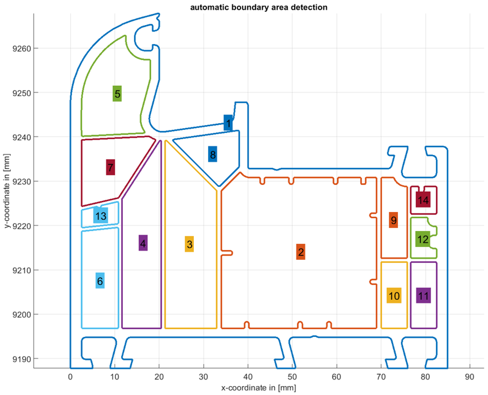
Abbildung: Automatische Erkennung der Profilgeometrie und automatische Parametrierung von Randbedingungen
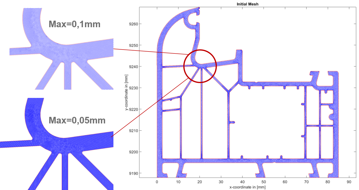
3. Nachdem die Geometrie importiert und die Randbedingungen gesetzt wurden, wird der automatische Vernetzungsalgorithmus der chillWARE aktiviert, mit dessen Hilfe die Profilgeometrie in ein finite Elemente Netz (Tetraeder) diskretisiert wird. Durch Benutzereingriff ist eine Anpassung der maximalen Elementgröße möglich, wie in der unteren Grafik ersichtlich. Werden die Standardeinstellungen beibehalten, wählt das System automatisiert eine optimale Elementgröße auf der Basis der Geometriedaten.
4. Zur Definition des Produktionsparameter wird als nächstes, aus einer im Programm enthaltenen Materialdatenbank ein Kunststoff-Material ausgewählt. Für sämtliche in der Software hinterlegten Materialtypen sind die vollständigen thermodynamischen Charakteristiken (für den Abkühlprozess!) aus eigenen Labormessungen hinterlegt. Eine eigenständige Erweiterung der Materialdatenbank ist aber jederzeit durch den Anwender möglich. Die in der Software hinterlegten Daten enthalten mindestens die Wärmeleitfähigkeit des Materials, die Dichte, die spezifische Wärmekapazität sowie die Enthalpie in Abhängigkeit der Temperatur sowie weitere Werte wie den E-Modul, den Wärmeausdehnungskoeffizient, etc. in skalarer Form.
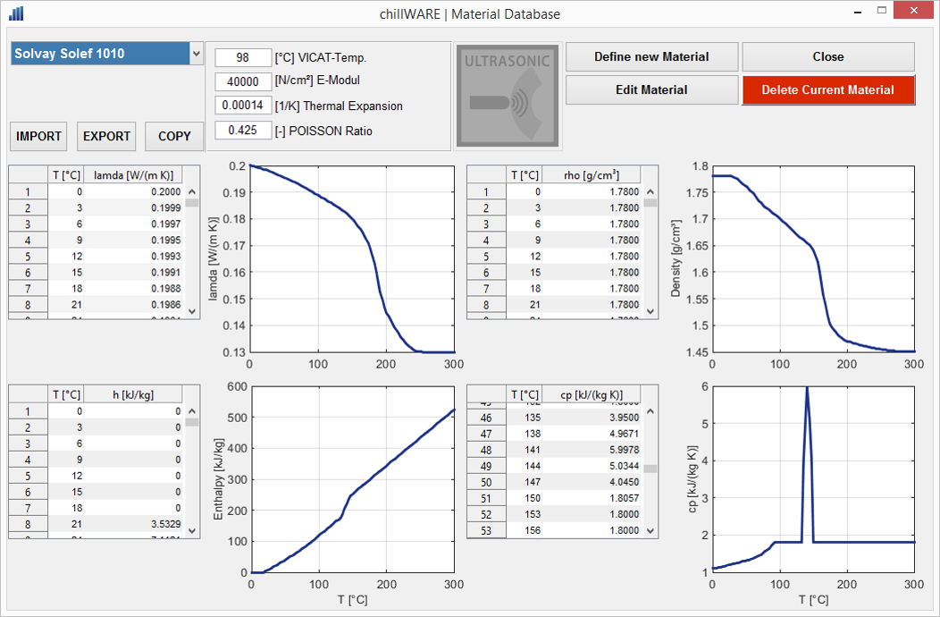
Abbildung: Beispiel eines Materialmodells aus der chillWARE Materialdatenbank
5. Im nächsten Schritt wird ein virtuelles Abbild der Kühlstrecke der Produktionslinie erstellt. Dazu wird aus einer Bibliothek an Standardelementen sowie durch Definition der realen Kühlwassertemperaturen und Segmentlänge eine virtuelle Kühlstrecke erstellt. Die Standardbliblithek verfügt dabei über sämtliche Systeme die an Profilextrusionslinien zum Einsatz kommen, angefangen von unterschiedlichen Kalibern über Tauch- und Sprühkühltanks bis hin zu Abzügen, Sägen oder auch speziellen Heizstationen (IR, Gas, etc).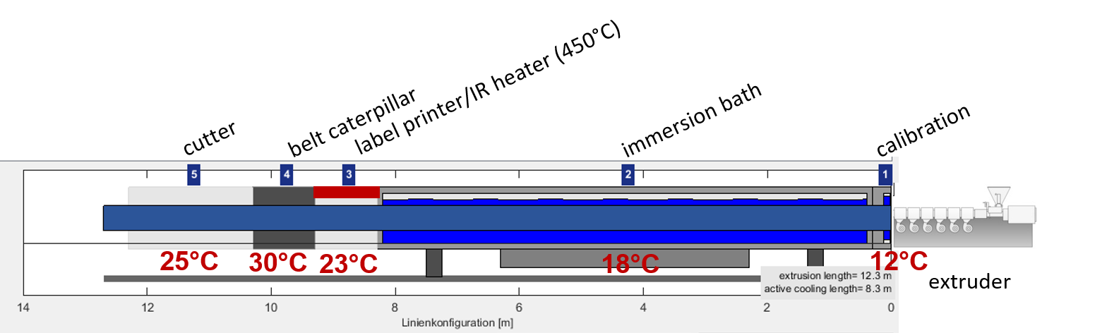
6. Starten einer Einzelsimulation oder automatisierte Durchführung einer iterativen Optimierung
Die thermische Prozesssituation des definierten Projektes bestehend aus den Teildefinitionen (Material, Geometrie, Prozess, Kühlstrecke) wird nun von der chillWARE 3D Engine berechnet und grafisch visualisiert.
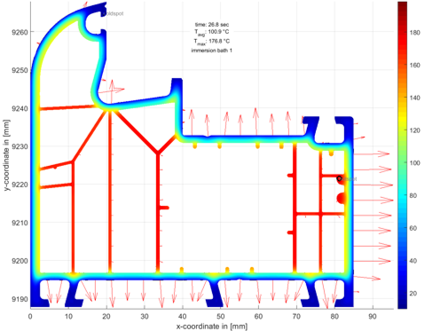
Die Ergebnisse beinhalten dabei die vollständige thermodynamische Situation des Profils an jeder beliebigen Stelle innerhalb der Kühlstrecke und an jedem beliebigen Punkt innerhalb der Geometrie. Die Darstellung der Ergebnisse erfolgt in Diagrammform, als Farbkonturplot oder als Animation der Abkühlsituation, wobei in den einzelnen Darstellungsarten besonders relevante Bereiche (z.B. der Hot-Spot (heißeste Punkt) oder der Cold-Spot (kälteste Punkt)) in der Grafik automatisiert ermittelt und angezeigt werden.
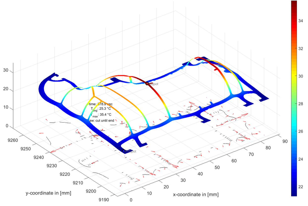
Zudem werden die Kühlgradienten in Form von Pfeilen variabler Länge (Länge repräsentiert den Gradientenwert) dargestellt sowie dreidimensionale Diagramme zur Besserung Veranschaulichung besonderer Teilergebnisse ermöglicht.
Selbstverständlich stehen in allen Ergebnisdarstellungen die typischen Funktionen Drehen, Schwenken, Vergrößern, Verkleinern zur Verfügung und die Achsen können skaliert werden.
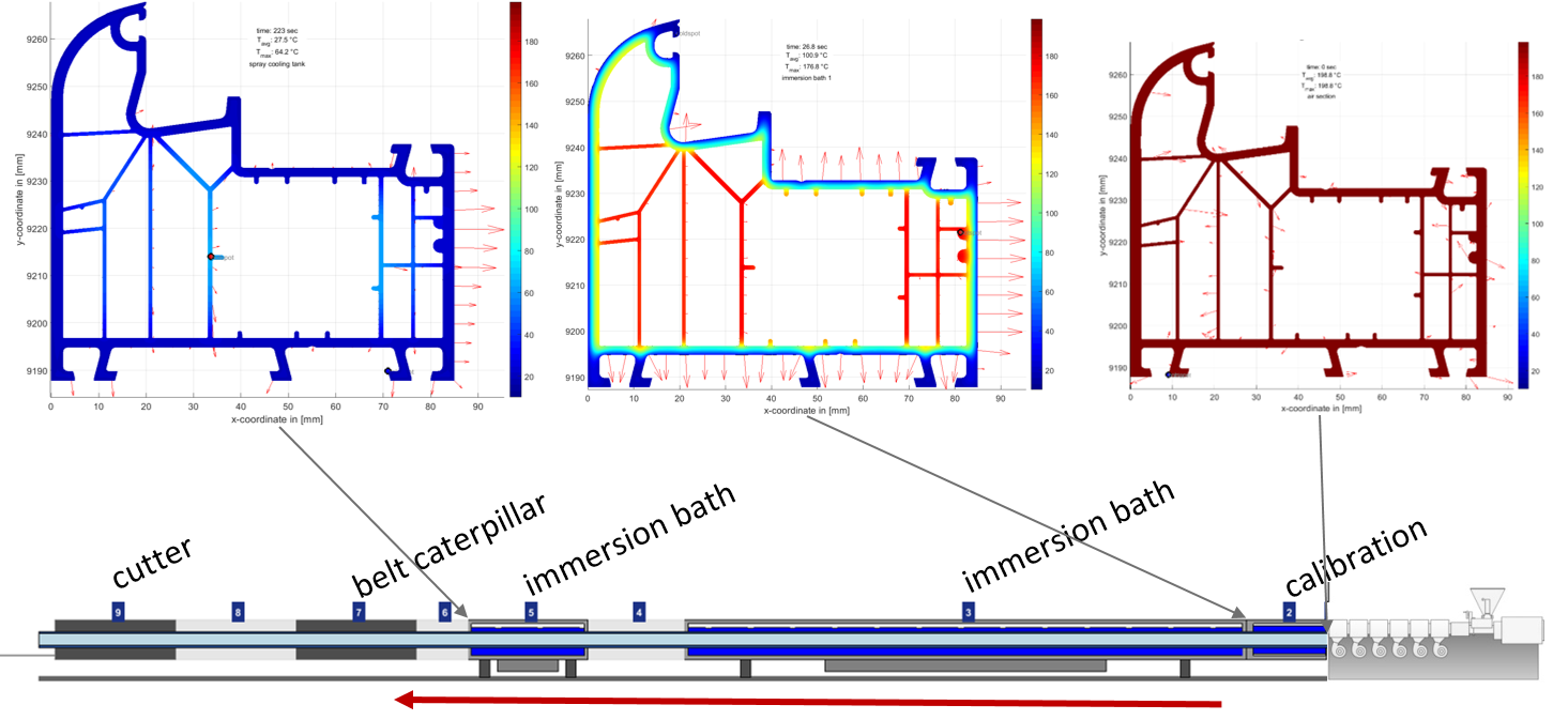
Abbildung zeigt Berechnungsergebnisse von profileSIM (Berechnungszeit ca. 35 Sekunden)
Automatische Optimierungssysteme bieten zudem die Möglichkeit, mehrere Simulationen unter Vorgabe eines Sollwertes iterativ durchzuführen, wobei einzelne Produktionsparameter variiert werden, bis eine Zielgröße erreicht werden kann.
Zurückblickend auf die Einleitung sowie die Artikelüberschrift wäre somit eine Optimierungsrechnung in folgendem Stil möglich:
Bestimmung der maximalen Produktionsgeschwindigkeit
Vorgabe: Geometrie, Material, verfügbare Kühlstrecke
Kritischer Wert: Hot-Spot Temperatur an der Säge
Ablauf:
Die chillWARE Simulation berechnet für eine Start-Produktionsgeschwindigkeit die Temperaturverteilung des Profils im Bereich der Säge und ermittelt, ob die maximale Temperatur oberhalb oder unterhalb der kritischen Temperatur liegt. Sofern die kritische Temperatur überschritten wurde, wird (z.B.) eine Anpassung der Kühlungsparameter (Wassertemperaturen, Stützluft, etc.) vorgenommen, um die gewünschte Produktionsgeschwindigkeit realisieren zu können. Sofern diese Maßnahmen nicht ausreichend sind, werden alternative Produktionsparameter (z.B. realistische Liniengeschwindigkeiten) ermittelt. Sofern die kritische Sägetemperatur noch nicht erreicht ist, steigert der Algorithmus die Prozessparameter, so dass eine optimale Produktivität und Prozesswirtschaftlichkeit das Ergebnis darstellen.
Fazit
Auf der Basis von thermodynamischen Simulationen der Profilabkühlung lassen sich eine Vielzahl wertvoller Informationen ermitteln, die helfen das Prozessverständnis zu Verbessern, Kalkulationen realistisch durchzuführen und die helfen Produtionsprobleme (Eigenspannungen, Bogenlauf, Einfall von Profilstellen, etc.) zu vermeiden.
Wenn Sie Interesse an weiteren Informationen und kostenloses Downloadmaterialien haben oder automatisch beim Erscheinen neuer Beiträge informiert werden möchten, melden Sie sich für unseren internen Bereich und Newsletter an.
https://www.youtube.com/watch?v=p_SzMW_7k9s
(Bei der chillWARE Abkühlsimulation handelt es sich um eine Computersimulationssoftware der Firma SHS plus, basierend auf der finite Differenzen und der finite Elemente Methode, welches speziell für den Einsatz in Extrusionsbetrieben entwickelt wurde. Die Software wurde zweimal in Folge mit dem Prädikat “Produkt des Jahres – 2.ter Platz” des Plastverarbeiters in den Jahren 2016 und 2017 ausgezeichnet und wird international von Kunststoffverarbeitern und Maschinenbauern eingesetzt. Sofern Sie an einer persönlichen Vorstellung des Systems interessiert sind, sprechen Sie uns gerne an.)
[:en]
When extruding profiles, the maximum production speed is one of the most important factors for the calculation af a quotation. If the production speed is assumed to be higher than the real production can be in practice, this can mean high losses for the extrusion plant and represents a high economic risk.
Nowadays, manufacturers of extruded profiles are very often contract extrudeurs and receive requests from their customers for the production of special profile geometries.
The first steps of the extrusion plant are then usually:
- the analysis of the feasibility of the profile,
- the calculation of the achievable extrusion speeds and based on this
- Calculation of the cost of goods manufactured or determination of the offer price
The extrusion company must therefore provide the customer with a binding sales price in €/m product, even before the production of the extrusion die and the calibre is done and before the line is run in or the product is sampled. To calculate this price, the reliable determination of a realistic production speed of the profile is one of the most important factors determined by the profitability of the entire job.
However, calculating the maximum production speed is not an easy step, especially when complex hollow chamber profiles are involved. Internal areas of the profile cannot be actively cooled and the air chambers insulate the internal areas very well thermally. This in combination with the already very low thermal conductivity of plastics leads to sometimes very long cooling times or to only low possible line speeds.
Due to the complexity of the profile geometries, even experienced designers and extrudeurs regularly reach their limits in such a design task, since the thermodynamic situation is hardly calculable analytically.
Exactly for such tasks (and many others) the module profileSIM of the chillWARE cooling simulation was developed, the use of which shall be illustrated in the following by means of an example profile (exemplarily carried out on a window profile drawing of the company Aluplast / IDEAL 8000 freely available in the net):
1. The request for an offer is usually made by sending a drawing of the desired profile cross-section as a two-dimensional drawing file.
2. This sketch of the profile geometry is imported into the chillWARE cooling simulation and the boundary conditions of the individual simulation areas are defined. The program automatically recognizes the profile area, the outer boundary of the profile and the different internal hollow chambers and parameterizes these with typical values. Of course, the boundary conditions can be adapted at any time on the basis of our own wealth of experience.
Illustration: Automatic recognition of profile geometry and automatic parameterization of boundary conditions
3. After importing the geometry and setting the boundary conditions, the automatic meshing algorithm of chillWARE is activated, with which the profile geometry is discretized into a finite element mesh (tetrahedron). User intervention allows the maximum element size to be adjusted, as shown in the figure below. If the default settings are retained, the system automatically selects an optimal element size based on the geometry data.
4. The next step in defining the production parameter is to select a plastic material from a material database contained in the program. For all material types stored in the software, the complete thermodynamic characteristics (for the cooling process!) are stored from our own laboratory measurements. However, the user can extend the material database independently at any time. The data stored in the software contain at least the thermal conductivity of the material, the density, the specific heat capacity and the enthalpy as a function of temperature as well as other values such as the modulus of elasticity, the coefficient of thermal expansion, etc. in scalar form.
Illustration: Example of a material model from the chillWARE material database
5. In the next step, a virtual copy of the cooling section of the production line is created. A virtual cooling section is created from a library of standard elements and by defining the variable parameters like real cooling water temperatures and segment length. The standard library has all systems used on profile extrusion lines, starting with different calibres, immersion and spray cooling tanks up to haul of units, saws or special heating stations (IR, gas, etc).
6. Starting a single simulation or automated execution of an iterative optimization
The thermal process situation of the defined project consisting of the partial definitions (material, geometry, process, cooling section) is now calculated and graphically visualized by the chillWARE 3D Engine.
The results include the complete thermodynamic situation of the profile at any point within the cooling section and at any point within the geometry. The results are displayed in diagram form, as a color contour plot or as an animation of the cooling situation, whereby particularly relevant areas (e.g. the hot spot or the cold spot) are automatically determined and displayed in the graphic in the individual display types.
In addition, the cooling gradients are displayed in the form of variable-length arrows (length represents the gradient value) and three-dimensional diagrams to improve the visualization of special partial results.
Naturally, the typical functions of rotation, pan, zoom in, zoom out and the axes can be scaled are available in all result displays.
Figure shows calculation results of profileSIM (calculation time approx. 35 seconds)
In addition, automatic optimization systems offer the possibility of iteratively carrying out several simulations with the specification of a target value, whereby individual production parameters are varied until a target value can be achieved.
Looking back on the introduction and the title of the article, an optimization calculation in the following style would be possible:
Determination of the maximum production speed
Specification: geometry, material, available cooling section
Critical value: Hot spot temperature at the saw
Procedure:
The chillWARE simulation calculates the temperature distribution of the profile in the area of the saw for a start production speed and determines whether the maximum temperature is above or below the critical temperature. If the critical temperature has been exceeded, the cooling parameters (e.g. water temperatures, supporting air, etc.) are adjusted to achieve the desired production speed. If these measures are not sufficient, alternative production parameters (e.g. realistic line speeds) are determined. If the critical sawing temperature has not yet been reached, the algorithm increases the process parameters so that optimum productivity and process economy are the result.
Summary
Based on thermodynamic simulations of profile cooling, a large amount of valuable information can be determined which helps to improve the understanding of the process, to carry out calculations realistically and to avoid production problems (residual stresses, bowing, deformations, shrinkage of profile points, etc.).
This link takes you to a video animation of the shown profile geometry:
If you are interested in further information and free download materials or would like to be informed automatically when new articles appear, please register for our internal area and newsletter.
https://www.youtube.com/watch?v=p_SzMW_7k9s
(The chillWARE cooling simulation is a computer simulation software from SHS plus, based on the finite differences and the finite element method, which was specially developed for use in extrusion plants. The software was awarded the title “Product of the Year – 2nd place” twice in a row by the plastics processor in 2016 and 2017 and is used internationally by plastics processors and machine builders. If you are interested in a personal introduction of the system, please contact us.)[:]